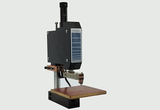
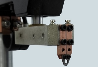
Welding Heads
CERTIFIED TO CE AND ROHS STANDARDS
WBT-F01 Features
1.High precision, long service life
2.Head lifting mechanism of internal smooth, steady, swing, sliding, not jerky, good reliability,
3.Low inertia, fast follow - through design to improve weld consistency, reduce
metal splash and improve solder joint appearance;
4.Welding head pressure spring, adjust the smooth, accurate, easy to adjust the
welding pressure, welding pressure to adapt to different elements;
5.Micro switch, pressure ignition, improve the quality of welding; when the pressure on the workpiece
surface to a certain extent, began to discharge;
Assembly steps
1; Loosen the fixing screw of the upper electrode and remove the upper electrode.
2: Remove the lower limit screw inside the lower limit sleeve on the right side of the host body.
3: Press down the scale rod in the direction of the arrow in the above figure until the pull rod
below the base is exposed. (See Figure 1 below)
4: Another person holds the foot pedal cable through the installation hole on the desktop and
exposes the cable connector. (See Figure 2 below)
5: Remove the top screw of the cable connector M3.
6: Place the pull rod into the cable connector and align it with the installation hole.
7: Screw on the M3 top thread and the depth is flush with the cable connector.
8: Release the scale rod to return it to its original position, then install the foot pedal cable into
the mounting hole of the base, and push firmly into the base of the tie rod.
9: There is a M4x10 top screw installed on the lower right side of the pull rod base, which
supports the pedal cable and tightens the top screw. (See Figure 3 below)
10: Install the lower limit screw of M6X35. (Tighten to the appropriate position according to the
welding stroke requirements)
11: Align the four mounting holes of the pull rod base with the mounting holes on the desktop
and tighten them.
(Figure 1)
(Figure 2)
(Figure 3)
Weld the Copper wire,need use the difference electrodes and holders
Application
Company photos